
This is an archived copy of content that was on CCDAntennas.com in the late 2000s. The dual band CCD antenna sold by Dave Kelley, AI7R, is no longer in production.
History
I live under a homeowners association with antenna restrictions. Dave Kelley, owner of CCDAntennas.com, is a friend of mine. After hearing my complaints about using roof flashing for an antenna, he suggested I try a CCD antenna. It was pretty brave of him because he knows I never take anything technical at face value. I have a burning desire to understand the theoretical and practical in everything I do. His antennas are made with heavy wire and large capacitors for full legal limit and I had to hide my antenna. I decided to build my own CCD with very thin wire and surface mount capacitors so it could be as invisible as possible. I quickly discovered the formulas available on Dave’s website were not intended for the small gauge insulated wire I was using. After building a few 40-meter CCD antennas that were just not quite right, I decided to play with antenna-modeling software. It was when modeling the CCD I discovered its potential to be resonant on two adjacent ham bands. Hours of computer models and wasted cut wire later, I had a CCD made with 26-gauge insulated wire strung between the peaks of my roof and the block walls that matched somewhat well on both 40 and 20 meters. With more computer modeling and less wasted wire (I was getting better at the modeling), I had a small gauge, dual band, 20/40 meter design that was under 1.5:1 SWR on both bands. I currently use this one on a 24-foot push-up pole while camping. Even more modeling and I had a design for both a 40/80 and a 20/40 full legal limit CCD for Dave. He built both of these designs on faith (you have to remember these antennas are not the easiest to build). When he put them in the air, they both worked even better than modeled.
How the CCD Antenna Works, a Simplified Explanation
Everyone has seen using series inductance to lower the resonant frequency of a short antenna. Screwdriver antennas and bug catchers are the first examples that come to mind. But what happens if you introduce series capacitance? As you might expect, adding series capacitance raises the resonant frequency. A standard-length CCD is a full wavelength of wire with enough capacitance evenly distributed throughout the wire to double its resonant frequency. Notice I did not say “full wave,” but said “standard length.” The capacitive reactance redistributes the current so the longer wire acts like a half wave at the design frequency.
In my discussion of the dual-band CCD I am going to use a simple visualization and talk about the capacitors shortening the wire much the same way some of us think about inductors lengthening the wire. Using this simplification we say the standard length CCD uses enough capacitance to “shorten” a full-wave dipole to resonate like a half-wave dipole.
The CCD antenna and Harmonic Operation
A normal dipole will resonate with a useable feed impedance at odd multiples of its design frequency. A 40-meter dipole will be useable on 15 meters. This is because the antenna becomes a wavelength and a half long. As long as a dipole is an odd multiple of half-wavelengths, the center feed point will be at a current peak and a low impedance.
A CCD antenna behaves differently as you raise the frequency. Remember the capacitive reactance is “shortening” the wire. However, as the frequency goes up, the capacitive reactance goes down. You can visualize this as the capacitors slowly disappearing as the frequency goes up and the wire “growing” to approach its real length. I noticed on the computer models that this effect is large enough to place the second SWR dip of a standard length 40-meter CCD at 12.5 MHz! This is between the 40- and 20-meter bands. This observation made me wonder if a 40-meter standard dipole has a second dip at 21 MHz and a standard length CCD has a second dip at 12.5 MHz, could I find a length of wire in between that has the second dip at 14 MHz? The answer was yes.
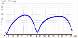
If you take just the right length of wire and add just enough capacitive reactance to resonate it on 40 meters, it will have its third-order resonance smack in the middle of the 20-meter band. Some of the benefits of this design are:
Every positive comes with a negative, right?
Yes, there is compromise in every antenna design. I will not get into the measurable or perceived benefits of CCD antennas over simple dipoles. That argument is subjective. What I will discuss are the major differences between a dual-band CCD and the two single-band CCDs it might replace. I will compare a single-band 20, a single-band 40, and a dual-band 20/40 all strung in an inverted V at 50 feet.
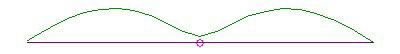
On the lower frequency or primary band, the dual-band design behaves much like the single-band design. It has the same broadside oval pattern and relatively high takeoff angle. Since it is shorter, it will have slightly less gain. Hams with limited space might think this is a good tradeoff.
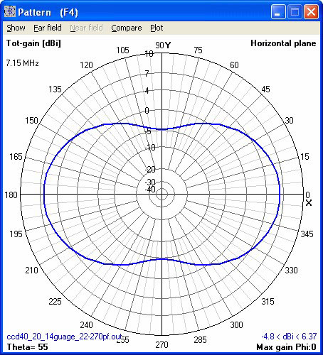
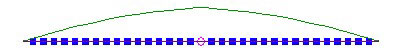
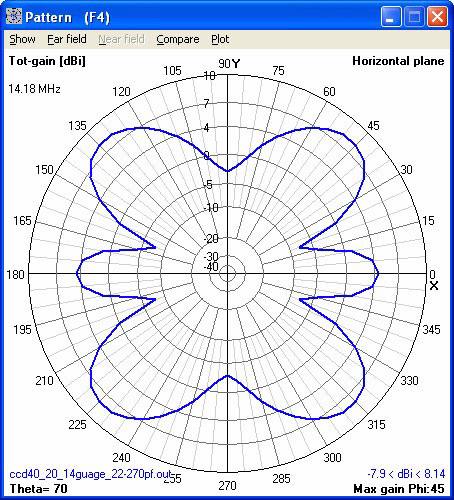
On the next band up, the dual band design is operating at 1½ wavelengths while the single-band antenna operates like a half-wave dipole. Because of this the dual-band design no longer gives you the characteristic dipole oval pattern. It exhibits a multi-lobe pattern as you would expect of a 1½-wavelength radiator. This can be good or bad depending on your operating conditions and goals. If the station you are having a QSO with is in one of the maximum gain lobes and a source of QRM is in one of the nulls, life is good. If it is the other way around, life is bad.
Remember, with all antenna modeling your mileage may vary. If you are lucky enough to have the wide-open space and homogenous ground the model approximates, I envy you.
My antenna is strung within feet of roof tiles, electrical wires, phone lines, patio furniture, and pool fencing. Try to computer model all of that with any accuracy!
So if you want to work two adjacent bands with a single horizontal antenna, think about the dual-band CCD.